Motor Protection Electrical Engineering Circuit Diagram Motor Protection Circuit Breakers Motor Protection Circuit Breakers (MPCBs) combine the short-circuit and isolation functionality of a molded case circuit breaker with the motor overcurrent protection of a traditional overload relay. These devices are traditionally used in two-component starter applications, with a contactor to control a motor

From a machinery design standpoint, system engineers and equipment designers must choose appropriate In the United States, there are three basic categories for circuit protective devices as they relate to this document: UL 489, UL 1077, and UL 508. As circuit breakers, they can provide motor branch circuit protection and can be used as
PDF IEEE SF Motor Protection Fundamentals Circuit Diagram
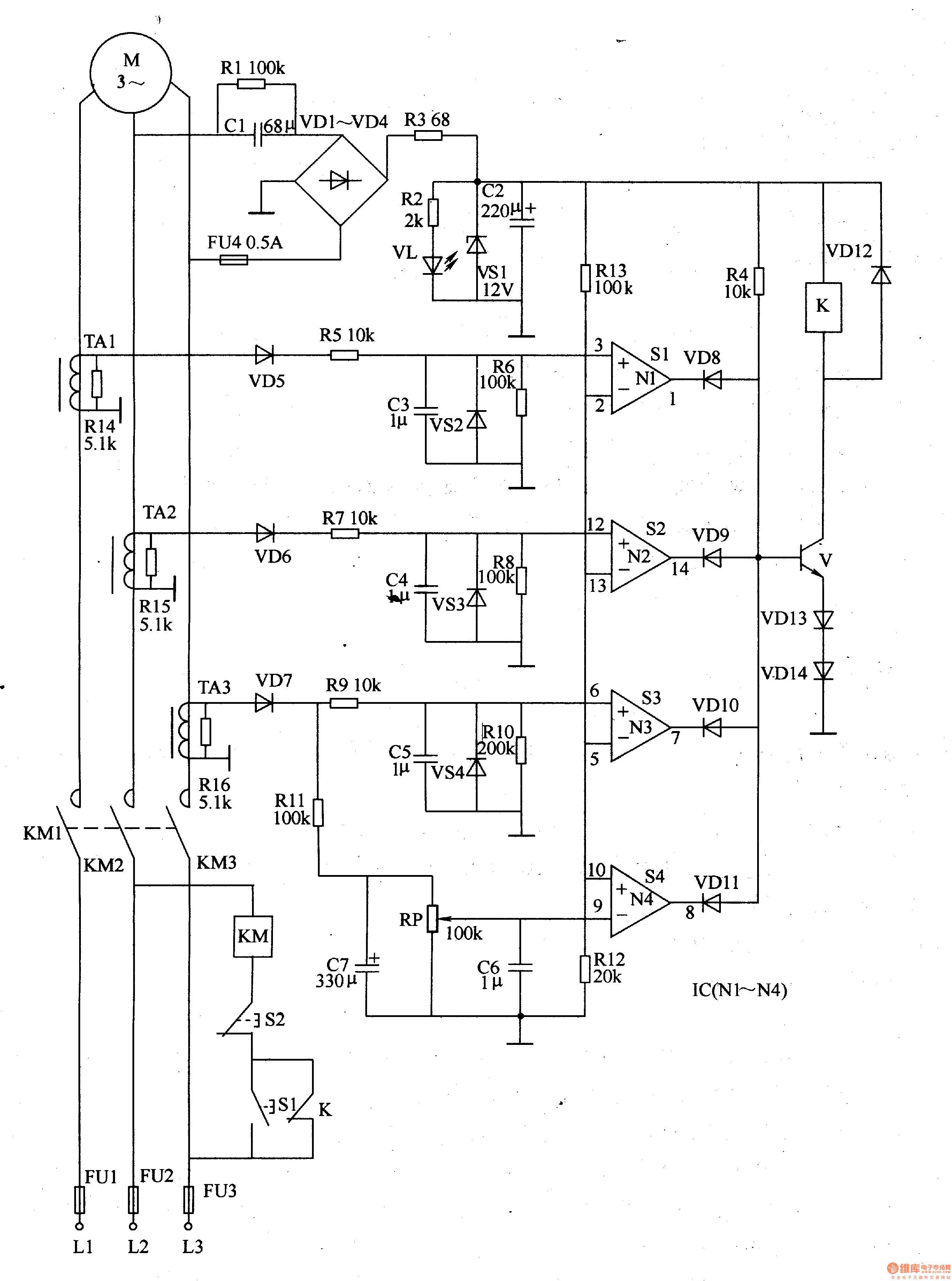
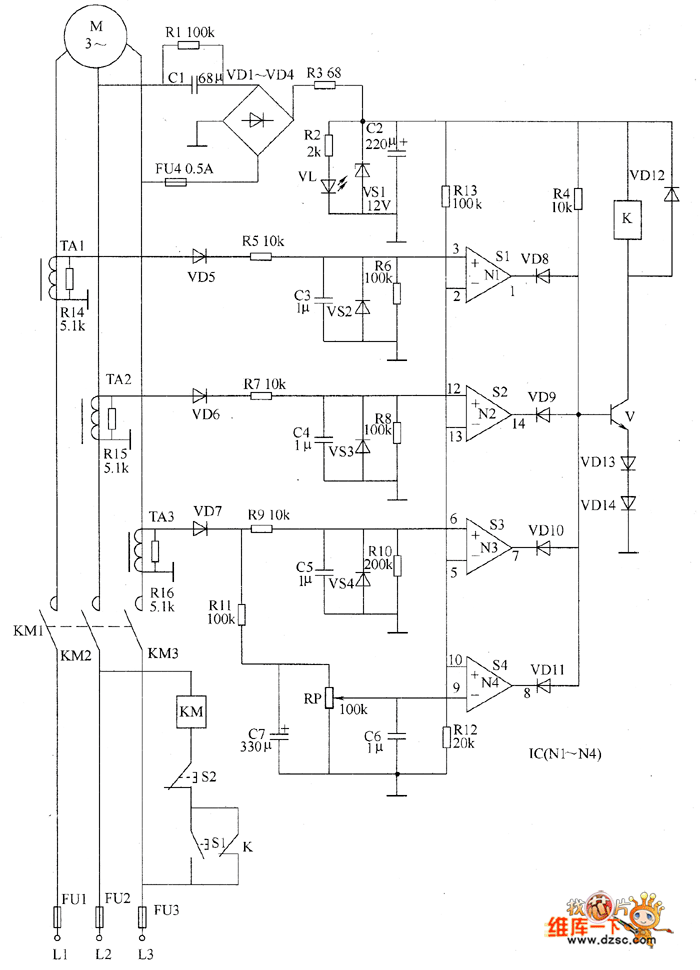
MPCB is the electromechanical protection device which is specially designed for motor protection. It is combination of two function like as one is adjustable overload relay and circuit breaker. It is the latest device of motor protection. Generally overload and circuit breaker are used as separately. 2- Circuit diagram of MPCB:
The entire circuit explanation is provided over/under cut-off voltage circuit. 2) DC Motor Over Heat Protection Module Circuit. The third problem involving temperature rise of the motor can be solved by integrating the following simple temperature indicator circuit. This circuit was also covered in one of my earlier posts. • Basic and advanced protection functions. • Motor Heating. • Pump Cleaning • Limp Mode • Motor Jogging and Breaking • Torque Control • 18 - 370A • Built in bypass. • User friendly HMI • Torque control. • Current limit (1.5-7*Ie) • Basic motor protection functions. • Analogue output. • Optional communication —
PDF Circuit Protection Methods Circuit Diagram
• Electrical, mechanical, and thermal motor characteristics define the frame needed for effective motor protection • Running stage, starting stage, and locked-rotor conditions serve to determine the main motor parameters • Motor heating and thermal damage motor characteristics depend on both positive-and negative-sequence current in the