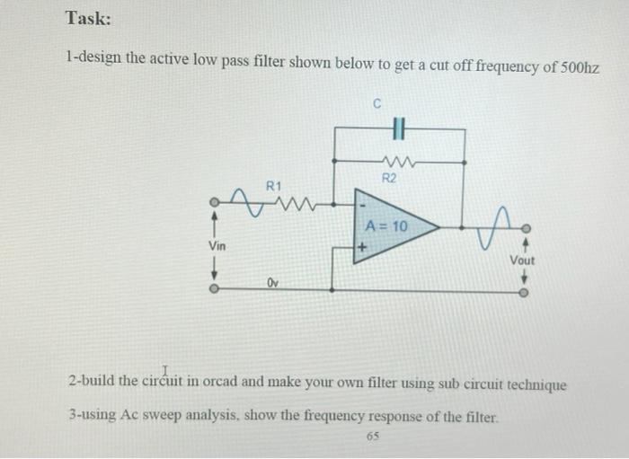
Schematic of active low pass filter Circuit Diagram Active Low-Pass Filter Design 3 The choice of circuit topology depends on performance requirements. The MFB is generally preferred because it has better sensitivity to component variations and better high-frequency behavior. The unity-gain Sallen-Key inherently has the best gain accuracy because its gain is not dependent on component values.

The low pass filter calculator helps you design and build a low-pass filter circuit, with support for passive (RC and RL) as well as active (op-amp based) filters. RL low-pass filters. Active low-pass filters can be built with active components, most notably the operational amplifier (or op-amp). They include:
PDF Active Low Circuit Diagram
By this action of the amplifier, the output signal will become wider or narrower. The maximum frequency response of the filter depends on the amplifier used in the circuit design. Active Low Pass Filter Circuit. The attenuation of the signal i.e. the amplitude of the output signal is lesser than amplitude of the input signal in the passive circuit.
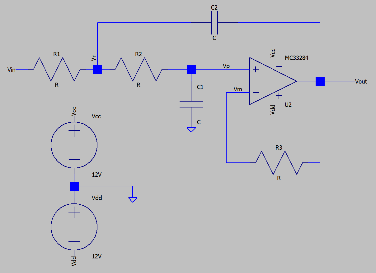
Active Low Pass Filter Circuit Diagram. The frequency response of Active low pass filter is same as that of the passive low pass filter, except that the amplitude of the output signals. The voltage gain of the non-inverting operational amplifier is given as. AF = 1+ (R2/R1) The gain of active low pass filter is given as
How to Build an Active Low Pass Filter Circuit with an Op Amp Circuit Diagram
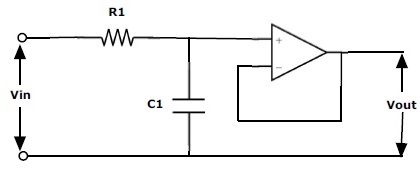
To surmount this problem, active circuit designs were introduced. When a passive low pass filter is connected to an Op-Amp either in inverting or non-inverting condition, it gives an active low pass filter design. The connection of a simple RC circuit with a single Op-Amp is shown in the image below.. First Order Active Low Pass Filter with the frequency response In an active low pass filter, the peak of the passband of the filter can be much larger than the input voltage signal because there is amplification. For passive low pass filters to be built, all that is required are resistors and capacitors. Active low pass filters require either transistors or op amps to provide amplification to the circuit.